Definition: Shockley diode is a four layer (P-N-P-N) device. It conducts when it is forward biased and stops conducting when it is reverse biased. The major difference between conventional diode and Shockley diode is, it starts conducting when the forward voltage exceeds break-over voltage. It was invented by William Bradford Shockley, and that’s why it is named after its inventor.
Shockley Diode is not widely available commercially. Still, it forms the backbone of devices like Diac, Triac, SCR. It operates in two states either ON or OFF. Thus, it is used as switching device. It is also called PNPN diode because of its construction architecture. It is a two terminal device that’s why it is categorised as diodes.
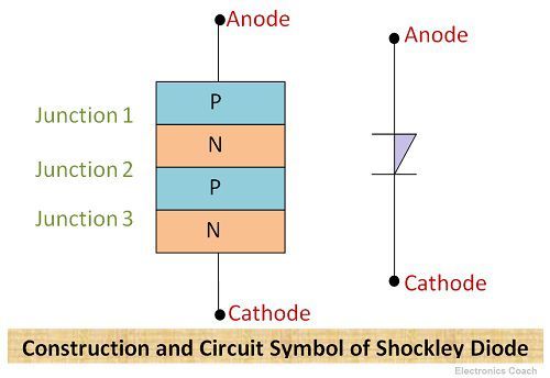
Construction of Shockley Diode
It is formed by sandwiching four layers of semiconductors P-type, N-type, P-type and one more N-type. Three junctions are formed due to the merging of four layers together. Its construction and circuit symbol are described in the below diagram.
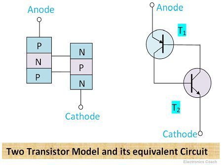
The construction of Shockley diode can also be understood by two transistor model. The four layers constitute internally two transistors T1 and T2 connected together. The emitter-base junction of Transistor T1 is Junction-1 (J1). The common connected base and collector of transistor T1 and T2 respectively constitute junction -2 (J2). The base-emitter junction of T2 is junction-3 (J3).
When the diode is to be operated in forward biasing then J1 and J3 are forward biased, and junction J2 is reversed biased. The Shockley diode is operated in forward biased mode only. When junction 1 & junction 3 are reversed biased and Junction 2 is forward biased the devices starts operating in reversed biased mode.
But when it is operated in reverse biased and the voltage exceeds the breakdown voltage the diode gets damage.
Working of Shockley Diode
When the anode of junction J1 and J3 is made positive and cathode as negative, the current starts increasing gradually. But before attaining break-over voltage, the resistance offered by the diode is quite high. Thus, only small amount of leakage current flows through the diode.
When the forward voltage exceeds break-over voltage VBo, the current starts increasing significantly. When the current increases from a particular limit the diode switches to ON state. This value of current is called holding current in Shockley diode.
To switch the diode in OFF state the voltage supplied should be decreased so that the value of current decreases below holding current limit.
V-I characteristics of Shockley diode
As discussed above when the Junction J1 and J3 are forward biased, the current in the diode starts increasing. Thus, it can be seen from the Characteristics curve that above break-over voltage current is increasing significantly. And when current attains a value equal to holding current value (IH) the Shockley diode is in ON state.
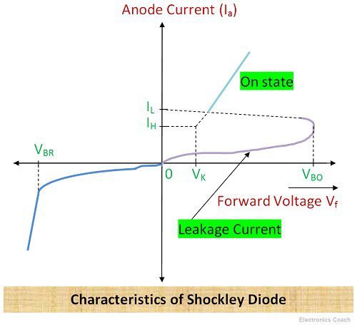
When J2 is forward biased and J1, and J3 is reverse biased, the diode operates in reverse biased mode. Due to which reverse current starts increasing and if the reverse voltage exceeds reverse breakdown voltage, excessive heat is produced due to the large magnitude of reverse current. This leads to the destruction of the diode. Thus it is never operated in reverse biased mode.
Advantages of Shockley Diode
- Shockley diode has high switching speed.
- It can do much more than a transistor as its construction architecture itself comprises of two transistors connected with a common terminal.
Disadvantages of Shockley Diode
Its construction is complex due to the involvement of four layers of semiconductor material.
Applications of Shockley Diode
- Shockley Diode as Trigger Switch: It is used to ON the SCR or triggers the SCR. In the below circuit, the RC network is fed to DC supply and capacitor starts charging. When the voltage across the capacitor becomes equivalent to the break over voltage of Shockley diode the capacitor starts discharging. Then, the diode switches to ON state and turns on the SCR by providing gate current to SCR.
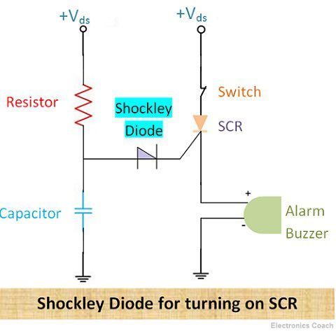
Thus, SCR is turned on, and the alarm starts. When the voltage supply is ceased then also the SCR remains in the latch that is in conducting stage for some time. Thus, the Shockley diode is only used for turning it On.
- Shockley Diode as Relaxation Oscillator: In this, the capacitor charges through a resistor and when the voltage across the capacitor is more than the break-over voltage, the diode turns on and acts as a short circuit.
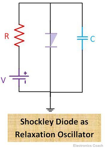
And then the capacitor discharges through the Shockley diode, and thus the cycle repeats itself.
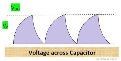
But the capacitor does not discharge completely. The waveforms of relaxation oscillator can be understood with the help of the diagrams.
VIVEK KRISHNA ELURI says
i am preparing for my semester on electronics and your content is really helpful for me , thank you