Definition: A backward diode is a semiconductor device which works in reversed biased mode. It is designed by providing variation in the design characteristics of Zener diode and tunnel diode. It is unilateral device because its designing mechanism allows it to operate in one direction only.
It is designed for specific purpose. It works in the same way in reverse biasing as the conventional diode operates in forward biasing. The negative resistance characteristics of tunnel diode are used in the backward diode.
Structure of Backward Diode
The construction of backward diode is similar to that of the tunnel diode. One side of the junction is lightly doped and another side of the junction is heavily doped. The characteristics so generated resembles the characteristics of the tunnel diode.
The operation of the diode takes place in reverse biasing mode thus, it is called backward diode.
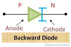
Circuit Symbol of Backward Diode
The circuit symbol of a backward diode is a slightly modified symbol of a conventional P-N diode. The anode terminal of the diode is same as conventional diode while the cathode terminal is slightly modified in order to differentiate diode from conventional P-N diodes.
Working of Backward Diode
The working principle of the backward diode is similar to that of the tunnel diode, the mechanism of quantum tunnelling plays a crucial role to conduct current in reverse biasing operation. The working of the backward diode can be understood in detail with the help of energy band diagram of the backward diode.
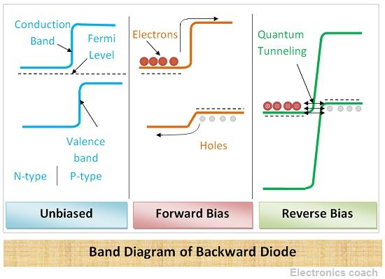
The energy band of the semiconductor under no biased condition can be seen in the above diagram. The band which is at higher energy level is called conduction band and the band which is at lower energy level is called valence band.
When external energy is supplied to electrons they attain the excited state of energy and enter conduction band. When electrons leave from valence band to conduction band they leave holes behind them in the valence band.
Under the no-biased condition, the filled valence band is opposite to filled conduction band. But when reverse biasing is applied to the semiconductor the P-region moves up with respect to N-region. The filled band in P-side is just opposite to empty band at N-side. Thus, the electrons start tunnelling from the filled band in P-region to empty band in N-region.
Thus, the current flows even in reversed biased condition. When forward biasing is applied, the N-side moves up with respect to P-side. Thus, the filled valence band of the N-type semiconductor will be just opposite to empty conduction band of P-type.Thus, the electrons flow from N-type to P-type.
The Backward Diode is operated in a reverse biased mode. The negative resistance region is created and this region is utilized for the operation of the diode.
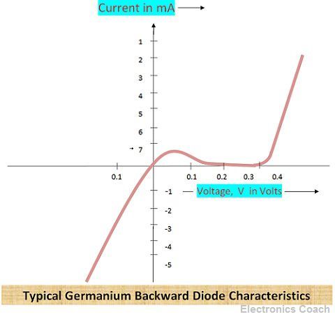
Characteristics of Backward Diode
The reverse characteristics are similar to the characteristics of the Zener diode. The forward characteristics can be understood with the help of the below diagram. Initially, current increases with an increase in voltage, but after a particular time, the magnitude of current becomes constant. It does not show a significant increase even if the variation in voltage is large.
Advantages of Backward Diode
- Temperature Sensitivity: The temperature sensitivity of Backward Diode is less than the temperature sensitivity of conventional diode. The sensitivity of backward diode is -0.1 mV/0C for both semiconductor material i.e. germanium and silicon. On the other hand, the sensitivity of conventional diode is -2mV/0C. Thus, backward diode is less affected with variation in temperature due to low-temperature sensitivity.
- Low Break Point: The break point of a backward diode is 0 V, while the break point of a conventional diode is between 0.6 V – 0.7 V. Thus, its low break point is effective for various application because the device can withstand high magnitude of voltage without the breakdown of the device.
While the conventional diode break point is not low thus, it cannot withstand high voltage and if the voltage exceeds 0.6 V-0.7 V the diode breaks down.
- Low Noise Level: The noise level of these diodes is low, thus signal to noise ratio in the case of the diode is far much better than conventional diodes.
- Efficiency: The efficiency of the diode is also better than a conventional diode, the structural characteristics impart an ability to the diode to improve its performance.
Application of Backward Diode
- Detector: It can be used as a detector up to the frequency of 40 GHz. It possesses low capacitance thus the problem of charge storage is minimized in these diodes. Besides, it’s nonlinear characteristics for small signal makes it appropriate for application of detector.
- Switch: The low capacitance of these diodes imparts an ability to the diode to switch from On state to off state efficiently. Thus, it is used in switching circuitry.
- Rectifier: It is used for rectification of signal with small peak voltage i.e. about 0.1 V- 0.7 V.
This is all about backward diode. Its ability to possess low capacitance is utilized in switching application. Besides, it also finds significance in rectifier circuits.
Bhim Dhurandhar kanwar says
Thanks