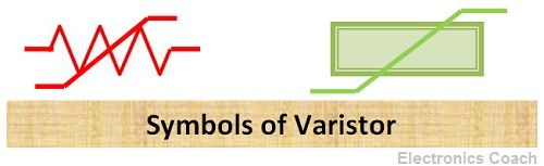
Definition: The term Varistor is formed by the combination of two words Variable and Resistor. It means it is a variable resistance. The resistance of varistors varies with the applied voltage. The resistance shows nonlinear behaviour with applied voltage.
The varistors protect the circuit by allowing excess current to flow through them and prevent the circuit from getting damaged.The current- voltage characteristics of varistor also possess nonlinear characteristics.
You must be thinking that if varistor shows variable resistance, then it must resemble potentiometer and rheostat. But it is not true. The potentiometer and rheostat are entirely different from a varistor. Although potentiometer and rheostat also show variable resistance but the resistance of potentiometer and rheostat can be varied manually between the minimum and maximum values.
On the contrary, the resistance of the varistors varies with the application of voltage. A question emerges in this context why to use variable resistor or varistor? What is its significance? The varistors are significant in the application where the excessive current in the circuit may lead to the destruction of entire circuitry.
Manufacturing Process of Varistors
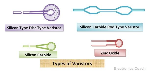
The crystals of semiconductor material such as silicon carbide are used with the ceramic binder, and both are pressed between electrodes, and the entire crystal is sintered at a higher temperature. The temperature of manufacturing and sintered temperature plays a vital role in shaping electrical characteristics of varistors.
Metal Oxide Varistors
The drawback of using semiconductor crystal is that the magnitude of leakage current in the circuit is more. The reason behind this is every semiconductor crystal has a junction, and due to the presence of this junction, the problem of charge storage becomes dominant.
Thus, when the device is switched from forward bias mode to reverse bias mode the charge stored at the junction takes some time to drain out completely. Thus, the current flows for a short duration even in reverse biasing mode.
This disadvantage of semiconductor varistor can be overcome if we use metal oxide varistor. In the case of metal oxide varistors, grains of zinc oxide or oxides of other metals are used. Generally, 90% of the grains are of zinc oxide, and 10% of grains are of other metals like bismuth, cobalt, manganese.
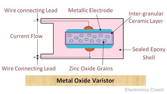
These grains are mixed with the granular layer; this layer acts as binding agent. It keeps the grains and the granular layer intact between two electrodes. The metallic contacts are provided to facilitate biasing.
The reverse leakage current in case of metal oxide varistors is less as compared to a semiconductor. The main reason behind this is the constructional structure of metal oxide varistors.
In metal oxides varistors the small metal oxide grains act as a group of a large number of diodes. Thus, it can be considered as a large number of small diodes are connected in parallel. Due to this the junction formed by tiny diodes is small and when the voltage is applied the small amount of voltage appears across each diode.
Thus, due to less voltage which appears across the junction formed by metal oxide grains, the reverse leakage current generated is also minimal.
Working of Varistor
When forward biasing is applied, the varistor offers high resistance in the path of current, and thus, very low amount of current passed through the devices. The voltage at this point is called rated voltage of varistor.
When the applied voltage increases further and becomes higher than the rated voltage of the varistor, the resistance of the device starts falling drastically and the currents start passing through the varistor.
When the applied voltage is below than the rated voltage, the varistor behaves as capacitor and stores charge carrier. Thus, the resistance of variable resistors shows nonlinear characteristics with the applied voltage.
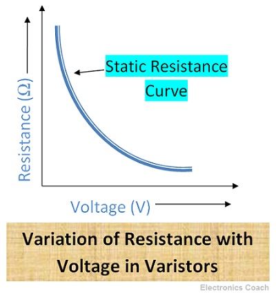
Resistance of Varistor
It is evident from the diagram below that the resistance starts falling with the increase of voltage.
V-I Characteristics of Varistors
The V-I characteristics of varistors is shown in the diagram below. It is evident from the diagram below that current varies non linearly with the applied voltage. In a typical resistor, the current varies linearly with the applied voltage i.e. it follows Ohm’s law while varistors do not obey Ohm’s Law.
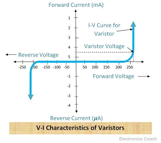
Initially, on the application of voltage the current does not show a significant increase, but after some time the slight change in applied voltage causes a significant increase in the value of Current. The voltage above which the current starts rising sharply is called rated voltage of varistors.
Applications of Varistors
Protection of Electrical and Electronics Circuit: Varistors protect electrical and electronics circuit by allowing excessive current to pass through them. Varistors are connected parallel to the electrical or electronic component in the circuit. When the voltage appears across the circuit, the varistors acts as a short circuit and offers negligible resistance.
Due to this the excessive current pass through the least resistance path i.e. pass through varistors instead of passing through the components and protect the component from damage.
In electronics circuit also the varistors are connected across the transistors in parallel so that in the case of excessive voltage or current appears in the device the entire current flows through varistors.
Characteristics of Varistors
- Electrical properties: The relationship between voltage (V) and current (I) of a varistor can be understood with the help of below equation.
V = CIβ
where C and β are constants
- Resistance value: Resistance (R) can be defined as the ratio of current (I) and Voltage (V).
R = V/I = CIβ/I
- Dissipated Power: The power dissipated in varistor is equal to the product of Voltage and Current.
P = V*I = V*(V/C)1/β
Relationship between leakage current and frequency
Xc = 1/ (2ΠFC)
where F is the frequency, C is the capacitance and Xc are the reactance.
Thus, if the frequency of the signal increases then reactance decreases and thus the leakage current through the devices starts increasing.
Leave a Reply