Definition: TRIAC is basically a 3 terminal ac switch that shows conduction in both the directions. These are triggered into conduction by low energy gate signal. TRIAC is a contraction of TRIode for Alternating Current. It is a bidirectional device that belongs to the thyristor family and is basically a diac with gate terminal used to control the turn-on conditions of the device.
More specifically we can say in TRIAC, Tri denotes 3 terminals of the device and ac denotes a device that is used to control alternating current. A 16 KW rating triac is easily available. For controlling applications these are widely used in power electronics field.
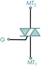
Let us have a look at the schematic symbol of a TRIAC:
Construction of TRIAC
The diagram below shows the basic structure of a triac: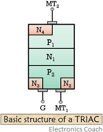
As we have already discussed that it is a 3 terminal and 4 layer device, it consists of 2 SCR in the inverse parallel connection having a gate terminal. It has 6 doped regions and the ohmic contact is made by the gate with both N and P regions. Due to this either polarity of the trigger pulse can start the conduction in the device.
Let’s have a look at the electrical equivalent of the basic structure of triac.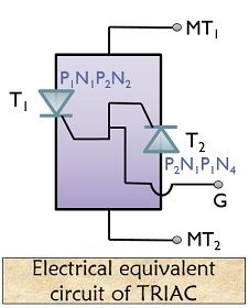
As it is a bidirectional device hence anode and cathode does not hold any significance. Thus, the terminals are represented as MT1 and MT2 along with gate terminal G.
Operation of a TRIAC
A triac is a device that conducts regardless of terminal voltage polarity. Resultantly there exist 4 different possibilities of operations.
Let us now discuss the cases separately:
1. When gate and MT2 are at the positive potential with respect to MT1:
On application of the positive potential at MT2 wrt MT1, the two junctions P1-N1 and P2-N2 gets forward biased. Hence current flows through P1-N1-P2-N2. Thus, a triac in such a condition is said to be biased positively.
2. When MT2 is at positive potential and gate is at the negative potential with respect to MT1:
As in the previous case, here also the current flows through P1-N1-P2-N2. But here, junction P2-N3 gets forward biased and the triac gets on by the injection of carriers in P2.
3. When gate and MT2 are at the negative potential with respect to MT1:
In such a condition, now the current flows through P2-N1-P1-N4. The junction P2-N1 and P1-N4 are forward biased and at the same time, N1-P2 is blocked thus it is said to be negatively biased. The applied negative gate potential forward biases the junction P2-N3 thus initiates conduction in the device.
4. When MT2 is at negative potential but the gate is at the positive potential with respect to MT1:
As in the previous case here also, the current flows through P2-N1-P1-N4. The junction P2-N1 and P1-N4 are forward biased resulting in carrier injection thus turning on the device.
Characteristic of a TRIAC
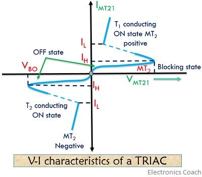
The characteristic curve of a triac basically holds the following 4 modes:
Mode 1: It is the first quadrant operation where VMT21 and VG1 both are positive.
Mode 2: It is the second quadrant operation where VMT21 is positive and VG1 is negative.
Mode 3: It is the third quadrant operation where VMT21 and VG1 both are negative.
Mode 4: It is the fourth quadrant operation where VMT21 is negative and VG1 is positive.
Here, VMT21 represent the voltage of terminal MT2 with respect to terminal MT1 and VG1 represents gate voltage with respect to terminal MT1.
A very large amount of current flows through the device when it starts conduction. However, such a large current can damage the device. Thus, an external resistance is employed in order to limit the excess current. Here, the control terminal is the gate and properly applied gate potential controls the firing angle of the device.
The voltage and current values for a typical triac are given below:
- On-state current: – 25 A
- On-state voltage: – 1.5 V
- Average triggering current: – 5 mA
- Holding current: – 75 mA
TRIAC control circuit
Let’s have a look at the triac control circuit shown below:
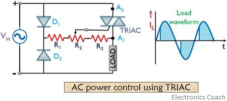
During the positive half and negative half of the input cycle, ac power is controlled to load by switching between on and off. The positive half forward biases D1 and reverse biases D2 and the gate is positive with respect to A1.
However, during the negative half cycle, D2now gets forward biased but D1 gets reverse biased and the gate is positive with respect to terminal A2. The resistor R2 employed in the circuit controls the point of beginning of conduction.
Advantages of TRIAC
- Its construction is simple, as it requires single fuse for protection.
- Both positive and negative polarity voltage can trigger the triac.
Disadvantages of TRIAC
- The availability of rating in triac is lower as compared to SCR.
- These are less reliable.
- There is no symmetry during firing at both halves of waveforms.
- Non-symmetrical switching makes it more susceptible to problems.
Applications of TRIAC
- It is used in AC controlling.
- It is used in lightening control.
- Triac find its applications in electric motors.
Effective results are obtained while controlling AC power with the help of triac. As triac’s are directly attached to ac sources so there is a need to ensure proper safety while circuit testing.
Leave a Reply