Definition: Anderson’s Bridge is an AC bridge that determines the self-inductance of an inductor in the circuit. This bridge offers highly accurate output and is an advancement of Maxwell’s inductance capacitance bridge.
By Anderson’s bridge, one can measure inductance by utilizing other circuit components like resistors and capacitor. In Maxwell’s bridge, the inductance is calculated by comparing it with a standard variable capacitance.
In this article, we will discuss the construction, theory as well as the mathematical expression to calculate the unknown inductance of a coil connected in the circuit.
Construction of Anderson’s Bridge
The figure below shows the constructional structure of Anderson’s bridge:
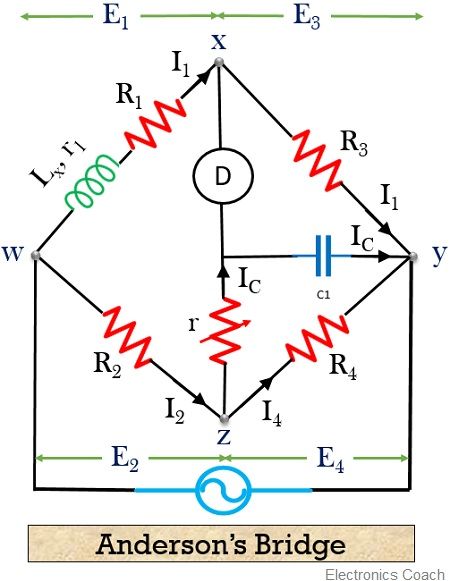
As we can see the bridge has junctions w, x, y and z that jointly forms 4 arms wx, xy, yz, zw.
The unknown inductance is connected in one of the arms along with a variable resistance R1. While the rest 3 arms of the bridge contain serially connected resistive elements.
Let us move further to understand the theory associated with Anderson’s bridge and how the unknown inductance is precisely calculated.
Theory and Mathematical Expression of Anderson’s Bridge
Here, for the above figure
- Lx is the unknown inductance to be measured,
- r1 is the resistance offered by the coil,
- R1 is the external variable resistance connected serially with the unknown inductance,
- r, R2, R3, R4 are the known resistances
and
- C is a fixed capacitor with known capacitance
At the balanced condition, the current through the detector must be 0. So,
I1 = I3 ——————– eqn 1
and
I2 = IC + I4 ——————– eqn 2
On equating the drop across R3 and C, we will get
![]()
So, from the above equation
IC = I1 jωC R3 ——————– eqn 4
Also, the voltage drop across arm wx must be equal to the sum of the voltage drop across yz and zw. So, we get
I1(R1 + r1 + jωLx) = I2R2 + IC r ——————– eqn 5
On substituting the value of IC in the above equation, we get
I1(R1 + r1 + jωLx) = I2R2 + I1 jωC R3 r ——————– eqn 6
On transposing, we get
I1(R1 + r1 + jωLx – jωC R3 r) = I2R2 ——————– eqn 7
Further, when the voltage across r and C is equated with the voltage at R4, we will have
![]()
On transposing
![]()
Again substituting the value of IC in the above equation
![]()
On dividing eqn 7 from eqn 10
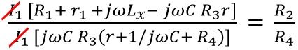
So,
R1R4+ r1R4 + jω Lx R4 – jωC R3R4 r = jωC R2R3 (r + R4) + R2R3
R1R4 + jω (LxR4 – CR3R4 r) = jωCR2R3 (r + R4) + R2R3 – r1R4
On equating the real part and imaginary part separately from the above equation
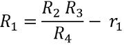
Real
R1R4 = R2R3 – r1R4
Imaginary Part
![]()
LxR4 – C R3R4 r = C R2R3r + C R2R3 R4
LxR4 = C R3R4 r + C R2R3r + C R2R3 R4
LxR4 = C R3[(R4 r + R2 r) + R2 R4]
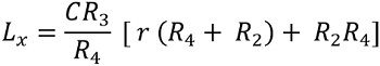
This is the desired equation used to determine the value of unknown inductance. And we can clearly see that the equation is independent of the value of r1 and R1.
Phasor Diagram of Anderson’s Bridge
The figure below shows the phasor representation of Anderson’s bridge:
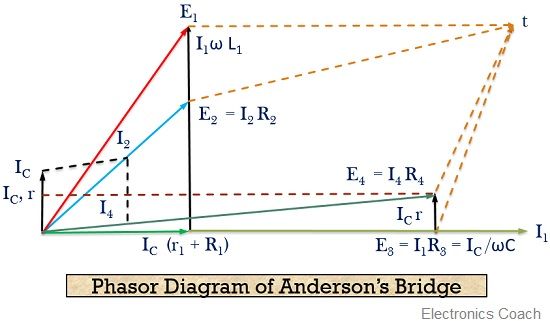
From the bridge circuit, it is clear that the current through arm wx i.e., I1 and the voltage drop at arm xy i.e., E3 are in the same phase. This is shown by the horizontal axis in the above figure.
Under the balanced condition, we know the drop across xy and oy must be equal.
The current flowing in arms wx causes the drop I1(R1 + r1) and in phase with arm current I1. And due to the balanced condition of the bridge, this current flows through arm xy.
Also, the drop across yz i.e., E4 is equivalent to the sum of drop at oz and oy i.e., IC/ωC and IC r respectively.
Thereby showing that the current I4 will be in phase with the drop across yz i.e., E4. Also, the phasor summation of drop across wx and xy or drop across yz and zw provides the supply voltage.
Advantages of Anderson’s Bridge
- The bridge is composed of a fixed capacitor that makes the determination of inductance quite easy.
- Also, one can find an accurate value of capacitance in accordance with the inductance.
- It is quite simple to find the balance point in Anderson’s bridge.
Disadvantages of Anderson’s Bridge
- The factor of complexity is highly associated with this bridge due to the presence of more components.
- Due to the existence of an extra junction O, the shielding of the bridge becomes a difficult task.
This is all about Anderson’s bridge inductance evaluation and phasor diagram.
Leave a Reply