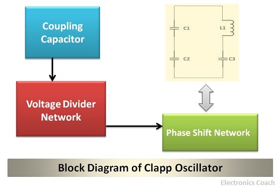
Definition: The Clapp Oscillator is an electronic device that consists of single stage amplifier and a phase shift network.The basic function of an oscillator is to generate the sinusoidal signal and the same work a Clapp oscillator does.
With the help of amplifier circuit, it provides the amplified signal to the phase shift network. This in return provides regenerative feedback to the amplifier circuit and thus sustained oscillations are produced.
Have a look at the block diagram representation of Clapp Oscillator:
Significance of Clapp Oscillator
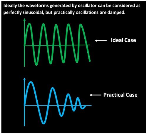
An oscillator is nothing but a tank circuit which consists of capacitor and inductor. And the charge stored in the capacitor is stored in the form of electrostatic field and when the capacitor discharges the energy it has stored in it will start decreasing.
This is because the inductor present in the circuit starts getting charged, and thus it stores energy in the form of magnetic field. In this way, energy is converted from one form to another, and thus oscillations are maintained.
But due to losses possessed by capacitor such as dielectric loss and radiation loss in inductors causes the oscillations to become damped. Due to which a constant amplitude sinusoidal waveform remains a distant dream.
Usage of other Oscillators
With the help of some oscillators such as the Colpitts, Clapp oscillator, the losses suffered by capacitor and inductor can be compensated by using a single stage amplifier circuit.
There are few oscillators which resemble each other in circuit architecture. Although there is a slight difference among those which changes their characteristics. One such example is colpitt and Clapp oscillator. The phase shift network of colpitt oscillator consists of two capacitors and one inductor. While the phase shift network of the clapp oscillator consists of three capacitor and one inductor.
The significance of using a Clapp oscillator over a colpitt oscillator is that the frequency stability of the Clapp oscillator is more. This is due to the presence of an extra capacitor.
Moreover, the feedback factor gets affected in Colpitts oscillator. This is due to the variation in the capacitance of the capacitor C1 and C2. This, in turn, affects the output of the oscillator circuit. Therefore, it is advantageous to use Clapp oscillator in place of the colpitt oscillator.
Working of Clapp Oscillator
The Clapp oscillator working can be easily explained with the help of its circuit diagram. It is clearly evident that the circuit consists of single stage amplifier and a phase shift network. The single-stage amplifier consists of the voltage divider network.
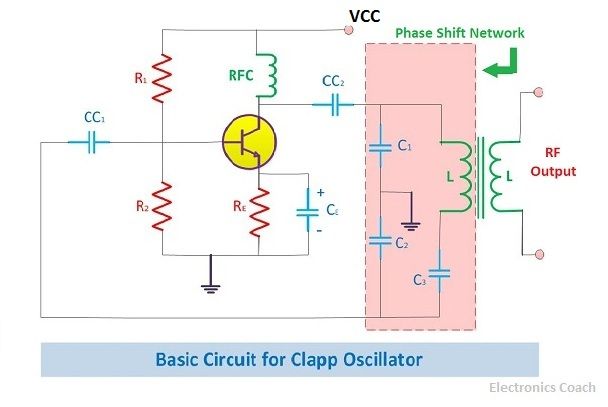
The transistor connected in this circuit is supplied by the power source Vcc. The power is supplied to the collector terminal of the transistor through the RFC coil. The use of the RFC coil is to block any AC component present in the power source and supply only DC power to the transistor circuit.
The transistor circuit supplies this power to the phase shift network through the decoupling capacitor CC2. This capacitor is used here so that only AC component of the power is supplied to the phase shift network. If any DC component is introduced in the phase shift network, then it will lead to the reduction in the Q-factor of the coil.
The emitter terminal of the transistor is connected with resistor RE which improves the stability of the voltage divider circuit. The capacitor is connected in parallel with this emitter resistor to bypass the AC in the circuit.
The amplified power generated by the amplifier will appear across the capacitor C1. And the regenerative feedback passed to the transistor circuit will be through the capacitor C2. It is to be noted here that the voltage across the capacitor C1 and capacitor C2 will be in opposite phase. This is because the capacitor C1 and C2 are grounded through the common terminal.
The voltage across the capacitor C1 will be in the same phase to the voltage generated by the amplifier circuit. The voltage across C2 is opposite in phase with that of the voltage across the amplifier circuit. This voltage in opposite phase is passed to the amplifier circuit as the amplifier circuit itself provides the phase shift of 180 degrees.
Thus, the feedback signal which already has a phase shift of 180 degrees is passed through the amplifier circuit. Then the complete phase shift will be 360 degrees which is the requisite condition for an oscillator circuit to provide oscillations.
Frequency of the Clapp Oscillator
The frequency of the Clapp oscillator can be determined or calculated with the help of net capacitance of the phase shift network.
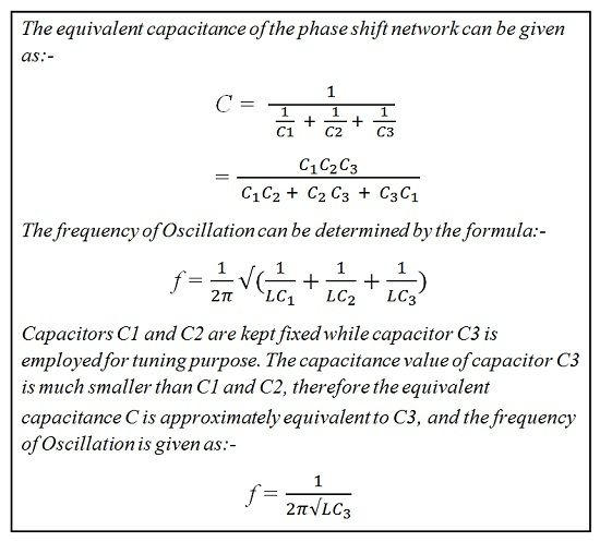
It is clear from the above equations that the frequency of the Clapp oscillator is dependent on the capacitance C3. This happens because in Clapp oscillator the values of capacitance of C1 and C2 are kept fixed. While the value of the inductor and capacitor C3 varies to generate the resultant frequency.
It is to be noted here that the value of capacitance C3 should be smaller than the value of capacitance C1 and C2. This is because if the capacitance C3 is of smaller value then the size of the capacitor will be small. This leads to the use of large size inductor. Therefore, the stray capacitance in the circuit will be negligible due to C3.
But one should be very careful while selecting the capacitor C3. This is because if very small capacitor is selected, then the phase shift network may not possess sufficient inductive reactance to generate sustained oscillations. Therefore, it should be smaller than the capacitance C1 and C2. And should be sufficient enough to possess the moderate reactance to [provide oscillation.
Advantages of Clapp Oscillator
The Clapp Oscillator possesses high-frequency stability than other oscillators. Moreover, the effect of transistor parameters in Clapp oscillators is very less as compared to other oscillators. Therefore, the problem of stray capacitance is not severe in case of Clapp oscillator.
We can increase the frequency stability of Clapp oscillator by enclosing the entire circuit of the oscillator in a constant temperature zone. Besides, the supply of voltage should be provided by a voltage regulator such as zener diode.
Leave a Reply