Definition: A lag lead compensator is a type of electrical network that generates phase lag as well as phase lead in the output signal at different frequencies when a steady-state sinusoidal input is provided to it. It is also known as lag lead network.
In case of a lag lead compensator, the phase lead and phase lag occur at different frequency regions. Generally, at low-frequency phase lag characteristics is noticed in the output of the circuit. While at high frequency, we have phase lead characteristics.
Thus, we can say a phase lag lead network is a cascade combination of phase lag and phase lead network.
Before proceeding towards understanding the design and characteristics of the lag lead network, we will see a brief introduction of the two networks.
A lag compensator is an electrical network that is designed to compensate a control system by adding a phase lag in the generated output signal when an input signal is applied to it.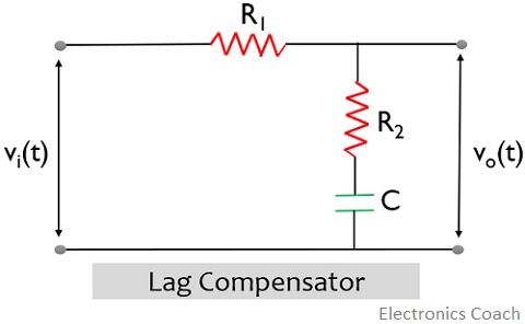
Unlike a phase lag network, a phase lead compensator introduces a phase lead in the sinusoidal output of the system, whenever a steady-state input is provided to it.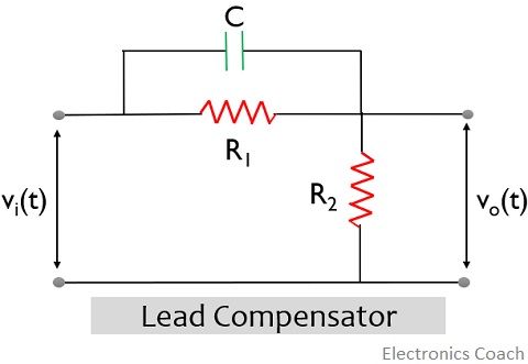
Need for Lag Lead Compensator
Generally, compensation in a control system is majorly done for two main reasons. Like for an absolutely unstable system, compensation is done in order to stabilize the system.
While sometimes the system is stable still, we don’t achieve the desired performance where the desired performance depends on various system parameters.
More simply, we can say, to have the accurate transient and steady-state response, a combination of lag and lead compensator is used.
We have already discussed in our previous article that a control system is added with a compensator in order to improve the specifications of the control system.
However, each of the compensating networks introduces some drawbacks along with improving the characteristics.
A lag compensator improves the steady-state performance of the system but at the same time, such a network causes a reduction in the overall bandwidth.
A lead compensator offers increased bandwidth, thus provides a fast response of the system, but this increases the susceptibility of the system towards noise.
Lag Lead Compensator
The figure below represents the circuit of a lag lead compensator: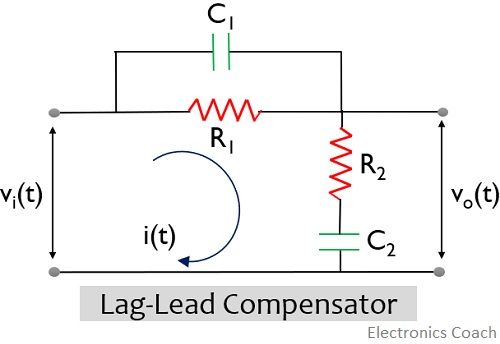
It is clear from the circuit shown above that if C1 is eliminated from the above circuit, then that particular circuit will be a lag network. While if C2 is not present, then we get a lead network.
This indicates that the above given network is a cascade combination of the lag as well as lead network.
So, consider the circuit shown above.
The loop current i(t) will be given as: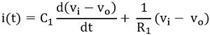
The output equation is given as:![]()
We know that the transfer function of the system is the Laplace transform of the response of the system to the Laplace transform of the input. So, taking the Laplace transform of the above equations, we will get,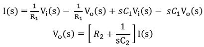
Now substitute the value of I(s) in the above equation, we will have,![]()
On simplifying,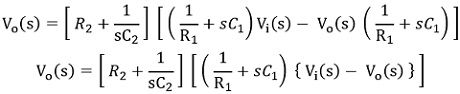
Further,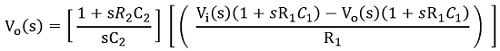
So,![]()
Therefore,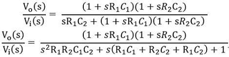
On simplifying we will get,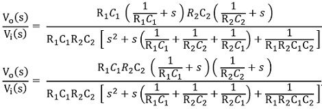
On cancelling like terms from numerator and denominator, we will get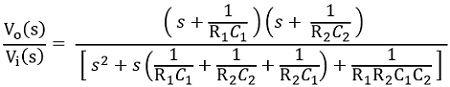
In generalized form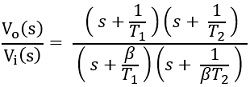
So, on comparing,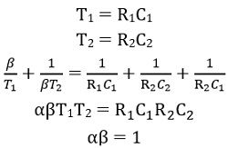
Therefore,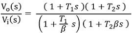
Here the value of β > 1
Here poles are s = – β/T1, – 1/βT2 and zeros are at s = – 1/T1, – 1/T2
The figure below shows the pole-zero plot of the lag lead compensator:
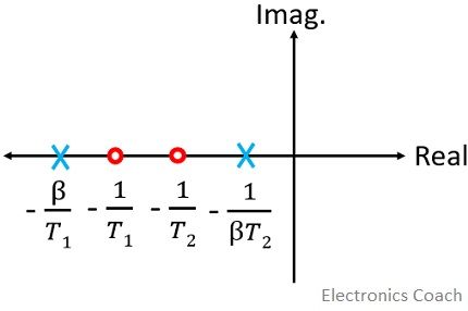
Thus, in case of the lag lead compensator, a lead angle is added by the phase lead portion whereas attenuation near the crossover frequency is provided by the phase lag portion.
Now, substituting s = jω in the above equation, the transfer function will be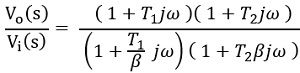
So, the magnitude will be: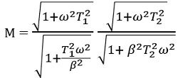
Hence, the phase angle will be![]()
Effects of Lag Lead Compensator
- The lead characteristics of the cascaded compensator provide improvement in the overall bandwidth.
- Also, due to the use of the lag network, the steady-state performance of the system gets improved.
So, we can say, a lag lead network provides a quick response with good accuracy. The low-frequency gain of the system is increased with this network, thereby improving the steady-state response.
Hence, we use a combination of lag and lead network as a compensator to provide required compensation to the control system.
Dr Ben says
This is a well written introduction to lea-lag compensators, and very useful.