The type of system having ‘1’ as the maximum power of ‘s’ in the denominator of the transfer function of the control system is known as the first-order system. Thus, we can say, that the order of the system is specified by the highest power of s.
Basically the order of the system shows information regarding the closed-loop poles of the system. Thus for the first-order system, we can say that there will be one closed-loop pole.
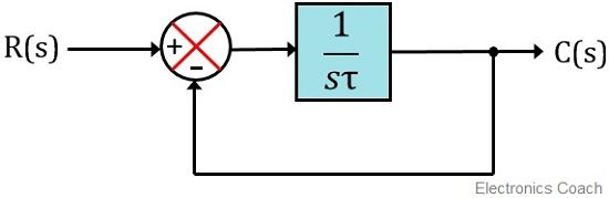
Here we can see the block diagram of unity negative feedback first order control system:
Here in this article, we are about to discuss the time response of the first-order control system. Now the question arises-
What is time response?
The time response of the system is defined as the output of the system obtained by providing specific input to the system, where both input and output must be the function of time.
This means that the time response of the system provides an idea about the variation in output when a certain input is provided with respect to time.
Basically the time response of the system is composed of steady-state response and transient response and is given as:
![]()
The transient response represents the fluctuation in the output of the system on applying input before achieving the final value.
While steady-state response represents the finally achieved output of the system.
Sometimes the finally achieved value shows variation from that of the desired value. Thus the difference of desired value and achieved value shows the steady-state error of the system, represented by ess.
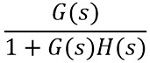
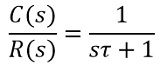
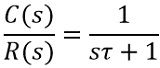
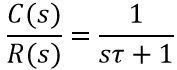
The closed-loop transfer function of the system is given as:
For unity negative feedback system, the characteristic equation gives the poles of the system
![]()
So, in general form, the first order equation will be:
![]()
Thus the closed-loop pole will be:

Time Response of First-Order System
We know that to determine the response of the system, some input must be provided to it. So, here we will consider different inputs and will see the response of each input on the first-order control system.
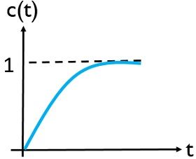
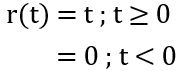
For unit step signal as input
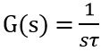
Since the open-loop gain of the first-order system is given as:
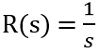
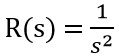
We know that for a unit step input
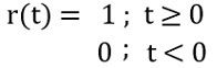
Thus
![]()
Taking the Laplace transform of r(t). So,
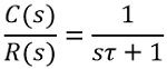
We know that the closed-loop transfer function is given as:
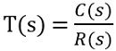
: C(s) is the controlled output and R(s) is the reference input
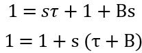
Since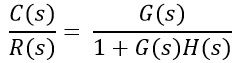
On substituting the open-loop gain, the above equation: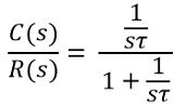
On simplifying,
Therefore,
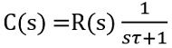
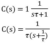
As we have already determined, R(s), for unit step unit. Hence substituting the value of R(s), we will have
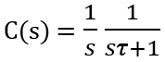
On solving the partial fraction of the above equation,
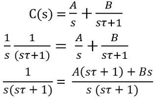
On simplifying,
![]()
On equating constant terms
![]()
Further substituting A = 1 in the general equation
Now, equating the coefficient of s, we will have
![]()
Therefore,
![]()
On substituting the values of A and B, we will have
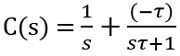
Further,
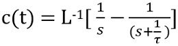
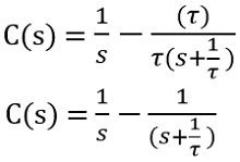 Now, taking inverse Laplace transform of the above equation,
Since,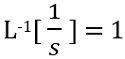
While
So,
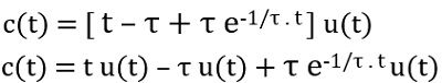
Thus,
Here u(t) represents the steady-state response while the other term is the transient response of the first-order control system.
The response of the unit step signal is given as:
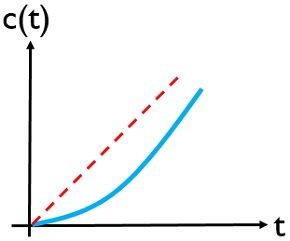
For unit ramp signal as input
We know the unit ramp signal is mathematically expressed as:
Therefore
The open-loop gain of the first-order control system is
Therefore,
Further on solving
On simplifying
On equating the constant term
![]()
On equating the coefficient of s after substituting the value of A
Further equating the coefficient of s2
So, on substituting the values of all the values in the general equation for unit ramp signal
Therefore,
Applying the inverse Laplace transform in the above equation
So, we will have
Here
![]()
represents the steady-state response while
![]()
shows the transient response of the first-order system with unit ramp unit.
The unit ramp response is:
For unit impulse signal as input
The unit impulse input in the time domain is given as:
![]()
Taking Laplace transform
![]()
Since the closed-loop transfer function is
Substituting the value of R(s)
Thus
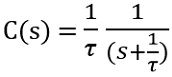
Taking inverse Laplace transform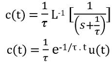
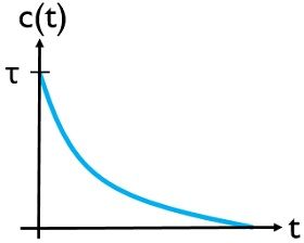
This is the time response of the first-order system with unit impulse input.
The unit impulse response is given as:
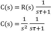
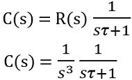
For unit parabolic signal as input
The reference input in the time domain is given as
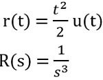
As the open-loop gain is
The transfer function is given as
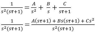
So,
On solving the partial fraction
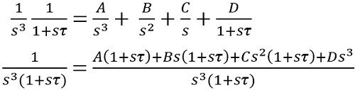
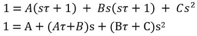
So, on simplifying
![]()
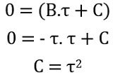
On comparing the constant
![]()
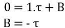
On comparing the coefficient of s
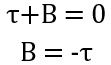
On comparing the coefficient of s2
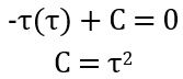
On comparing the coefficient of s3
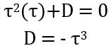
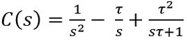
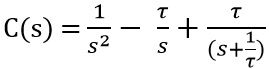
On substituting the values, we will get
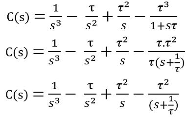
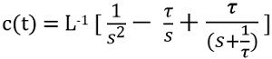
On applying the inverse Laplace transform, we will have
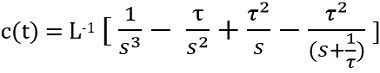
Therefore,
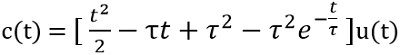
Here,
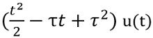
represents the steady-state response and
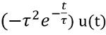
is the transient response.
Generally, for the time domain analysis of first-order control systems, step signals are majorly used as input. This is so because the response of ramp and parabolic input signals in the case of the first-order system increases even with infinite time.
However, as step and impulse functions provide stable responses thus are majorly used. But due to the absence of a steady-state term in the impulse response of the first-order system, step signals are mostly preferred.
Leave a Reply