Definition: A lead compensator is an electrical circuit that when provided with a sinusoidal input generates a sinusoidal signal as output with a phase lead in comparison to that of the applied sinusoidal signal. It is also known as lead network.
What is compensator?
We are aware of the fact that control systems are used to control the behaviour of the system in order to provide the desired output. But for proper controlling, the control system must also be properly designed.
The major specifications that must be achieved by the control systems in to order to perform properly are such there must be less errors, thereby generating accurate results. It must be quite stable and possesses good damping.
Generally, the gain of the system is adjusted first to produce desired results. However, simply dealing with the gain of the system is not going to work in favour of the system. The reason behind this is that with an increase in gain, though the steady-state behaviour improves however, this leads to affect the transient response adversely. This makes the system unstable. Hence redesigning the system becomes necessary.
Practically for redesigning the system, some alternation to it is necessary. This alternation in the circuit is done by the addition of an external device.
Thus redesigning of the system by the use of the external device is defined as compensation of the control system. And the external physical device which is added to the control system for redesigning purpose is known as a compensator.
By the addition of compensating network, poles and zeros are also introduced in the transfer function. Hence the performance parameters of the system get changed.
Phase Lead Compensator
By introducing a lead compensator in a control system, the sinusoidal output signal exhibits phase leading to that of the applied sinusoidal input.
A lead network has a pole and a dominating zero. A dominating zero is defined as the one which is nearest to the origin than all the other zeros. For a lead network, the poles and zeros must be present on the negative real axis of the s-plane.
Consider the lead network shown below: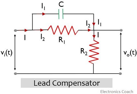
Let us now apply KCL in the above electrical network to determine the transfer function. So, in the above network, the total current through the load will be the sum of the current through each branch,![]()
So,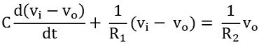
On taking Laplace transform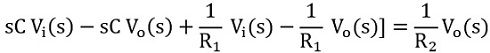
Now, separating the coefficients of output and input we will get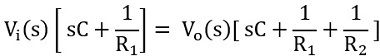
We know the transfer function of the system is the ratio of output to input. Thus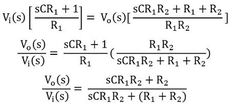
Taking CR1R2 as common from both numerator and denominator we will get: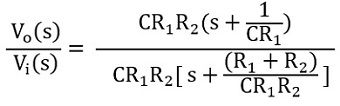
Therefore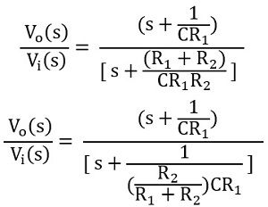
Generally, the transfer function of the compensator is given as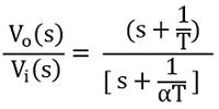
Thus, on comparing![]()
and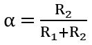
This signifies that the lead compensator has zero at s= -1/T and pole at s = -1/αT
The value of α lies between 0 and 1 (generally taken as 0.5), thus zero will be present to the right of the pole. The figure below represents the pole-zero plot: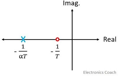
Lead Angle
Till now we have discussed the transfer function of the lead compensator. Let us now determine the maximum lead angle offered by the lead compensator at the respective frequency.
Since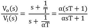
Substituting s = jω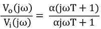
Thus the magnitude of the transfer function will be: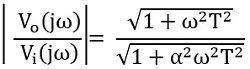
While the phase angle will be given as:![]()
Now determining the frequency at which ɸ is maximum.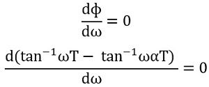
Thus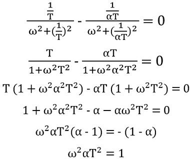
Thus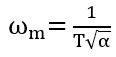 More simply
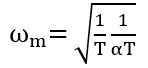
Therefore, at this particular frequency, the phase lead by the lead compensator will be maximum.
Hence we can say the geometric mean of two corner frequencies wc1 and wc2 give ωm.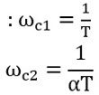
Since![]()
Therefore![]()
So,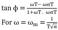
Thus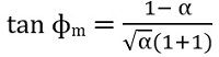
Hence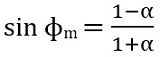
The above equation also provides the relation between α and ɸm.
Advantages of Lead Compensator
- As we have discussed that lead compensator introduces a dominant zero and a pole to the transfer function. Hence this improves damping of the overall system.
- The enhanced damping of the system supports less overshoot along with less rise time and settling time. Therefore, the transient response gets improved.
- The addition of lead network improves phase margin.
- A system with lead network provides a quick response as it increases bandwidth thereby providing a faster response.
- Lead networks do not disturb the steady-state error of the system.
- It maximizes the velocity constant of the system.
Disadvantages of Lead Compensator
- The introduction of the lead network in the system adds some attenuation to it. Thus to compensate the attenuation there must be an additional gain enhancement. But with an increase in gain, the requirement of more element increases. This leads to cause cost enhancement as well as more weight and greater space.
- The lead network reduces the overshoot, this increases the conditions of undershoot. This sometimes makes the system conditionally stable.
- A single lead network offers a lead angle of about 60°. Thus for the higher lead of around 70 to 90° multiple lead compensator is required to be added with the system.
- The lead network increases bandwidth but with increased bandwidth, the system becomes more susceptible to noise.
This is all about lead compensator.
Leave a Reply