Nyquist criterion or Nyquist stability criterion is a graphical method which is utilized for finding the stability of a closed-loop control system i.e., the one with a feedback loop. This criterion serves as a crucial way for design and analysis purpose of the system with feedback. Thus, it finds major application in Electronics and Control System Engineering.
The principle of Nyquist criterion was independently proposed by an electrical engineer of German origin, Felix Strecker in the year 1930 at Siemens. However, the graphical method for the determination of stability was given by Swedish-American engineer Harry Nyquist at Bell Laboratories in 1932.
Nyquist Stability Criterion
The stability theory by Nyquist is the basis of analysis and design of control system for the frequency domain approach. It is regarded as a graphical procedure to illustrate the stability of the system.
Nyquist stability criterion is a general stability test that checks for the stability of linear time-invariant systems. However, it is not applicable to non-linear systems as for that complex stability criterion like Lyapunov is used.
Suppose F(s) is a single-valued mapping function given as:
F(s) = 1 + G(s)H(s)
Where G(s)H(s) is the open-loop transfer function of the system.
We know
poles of 1 + G(s)H(s) = Poles of G(s)H(s) = Open-loop poles
while
zeros of 1 + G(s)H(s) = closed-loop poles of the system
We have already discussed earlier that for a system to be stable all the zeros of 1 + G(s)H(s) must exist in the left side of the s-plane and none should be present on the right side. Whereas the exact positioning of the zeros in the left half is unknown.
However, the stability of the system is analyzed by knowing the location of zeros of 1 + G(s)H(s) in the s-plane.
So, Nyquist suggested that despite analyzing the exact location of the zeros, if we examine the existence of even a single zero in the right half of s-plane then it will make the system unstable.
Thus, according to Nyquist the functional region of analysis for stability is the right-hand side region of s-plane.
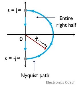
Therefore, Nyquist suggested that in spite of any arbitrary path τ(s) in s-plane, a path τ(s) must be selected that encircle the whole right half of s-plane.
The path must be such that it must begin from s = + j∞ and continued till s = – j∞ along the imaginary axis. This should be a semi-circle of the radius ∞.
This semicircular path is called the Nyquist path.
Basically, to find the number of closed-loop poles on the right half of s-plane the overall right half must be mapped into another complex plane with the use of mapping function F(s) = 1 + G(s)H(s).
So, N must be determined which is the number of encirclements of mapping around its origin.
Suppose, P denotes the number of poles of 1 + G(s)H(s) located in the right half of s-plane then the number of zeros lying on the right half of s-plane will be:
Z = N + P
Thus, to have absolute stability there must be no zeros of 1 + G(s)H(s) in the right half. This means for a stable system; Z must be 0.
Hence
N = – P
This is the Nyquist stability criterion.
Generalized Nyquist Path and its Mapping
We have previously discussed that the Nyquist path must be along the imaginary axis. But if there is a function having poles at the origin or poles on the imaginary axis, then, in that case, the Nyquist path cannot be formed along the imaginary axis.
This is so because according to mapping theorem, the given function should be analytic at every point on the path. However, the function will not be analytic at poles.
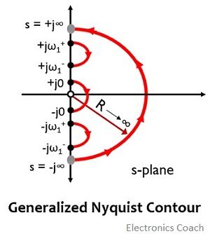
Therefore, a modification in the Nyquist path is done so that the poles get bypassed with the selection of semicircle having a radius that tends to 0 around them and encircling the complete right half of s-plane.
Hence, Nyquist path must be selected according to the situation of poles of G(s)H(s).
Consider that there are two poles of F(s) on the imaginary axis at ± jω1 and one pole at the origin.
Then the Nyquist path will be:
Let us see how the modification is performed:
- + jω1+ is a point considered which is very near and just above the + jω1
- + jω1– is a point present nearest and just below the + jω1
- – jω1+ is a point considered which is very close and just above the – jω1
- – jω1– is a point taken nearest and just below the – jω1
- + j0 is a point considered very near to the origin on the positive side of the imaginary axis
- – j0 is a point taken very close to the origin on the negative side of the imaginary axis
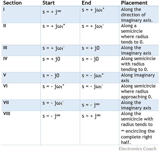
Thus, summarizing the sections of Nyquist path
 So, if we consider section I
Then the originating point is s = + j∞ i.e., ω = ∞
and the terminating point is s = + jω1+ i.e., ω = ω1+
Further, determine the magnitude and phase of G(jω)H(jω) at ω = ∞ and ω = ω1+
Now, rotate the plot from the starting point in order to reach the terminating point. In this way, we will get the mapping of section I in F-plane.
Again, for section II, using the same method mapping is achieved.
In a similar way, mapping of all the sections is done and a closed-loop plot i.e., Nyquist plot is obtained. Lastly, the encirclements of -1 + j0 are counted and checking is done for N = -P.
Leave a Reply