Definition: An optocoupler or optoelectronic coupler is an electronic component that basically acts as an interface between the two separate circuits with different voltage levels. Optocouplers are common component by which electrical isolation can be supplied between the input and output source. It is a 6 pin device and can have any number of photodetectors.
Here, a beam of light emitted by a light source exists as an only contact between input and output. Due to this, we can have an insulation resistance of megaohms between the two circuits. In high voltage applications where the voltage difference between the two circuits differs by several thousand volts, such isolation is favourable. The use of all such electronic isolators lies in all that conditions where the signal is to pass between two isolated circuits.
Till now we have talked about an isolated circuit but one should know the meaning of it before going into any further aspect.
What is an isolated circuit?
Isolated circuits are the circuits which do not have a common conductor in between them and proper isolation is maintained.
As we are already aware of the fact that the information signal highly contains noise and additional distortions in it which can be beyond the tolerance limit of the logic circuit at the output end during transmission. Optical couplers can be used to work on both ac and dc high voltages.
Construction of an Optocoupler
An optocoupler mainly consists of an infrared LED and a photosensitive device that detects the emitted infrared beam. The semiconductor photosensitive device can be a photodiode, phototransistor, a Darlington pair, SCR or TRIAC.
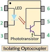
Let’s have a look at the basic diagram of an Optocoupler:

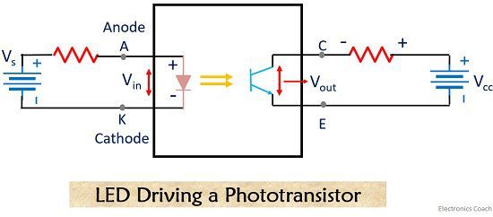
The infrared LED and the device that are light sensitive is packed in a single package. The LED is kept on the input side and the light-sensitive material is placed on the output side. A resistance is connected at the beginning of the circuit which is used to limit the current and the other resistance is connected between the supply voltage and the collector terminal.
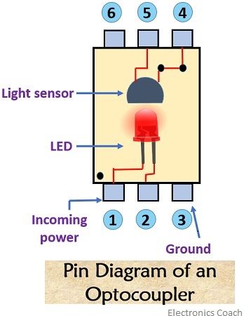
Before proceeding further let’s see the pin description of an optocoupler:

- Pin 1: Anode
- Pin 2: Cathode
- Pin 3: Ground
- Pin 4: Emitter
- Pin 5: Collector
- Pin 6: Base
The base terminal of the phototransistor is externally available. A single phototransistor is used at the output stage of a simple isolating optocoupler.
Working Of an Optocoupler
An Optocoupler is a combination of LED and a Photo-diode packed in a single package. As we can see in the below-shown circuit diagram, when a high voltage appears across the input side of the Optocoupler, a current start to flow through the LED.

Due to this current LED will emit light. This emitted light when falls on a phototransistor cause a current to flow through the same. The current flowing through the phototransistor is directly proportional to the supplied input voltage. An input resistance placed at the beginning of the circuit will decrease the amount of current flowing through the LED if its value is increased. As the LED glows due to this current, hence, when current will be low so as the light intensity of LED.
As we have already discussed earlier the intensity of emitted light by the LED will be equal to the corresponding current flowing through the phototransistor. This means that the low-intensity light emitted by the LED will cause a low-level current to flow through the phototransistor. Thus a changing voltage is generated across the collector-emitter terminal of the transistor.
In this way, an incoming signal from the input circuit is coupled to the output circuit.
Types of Optocoupler
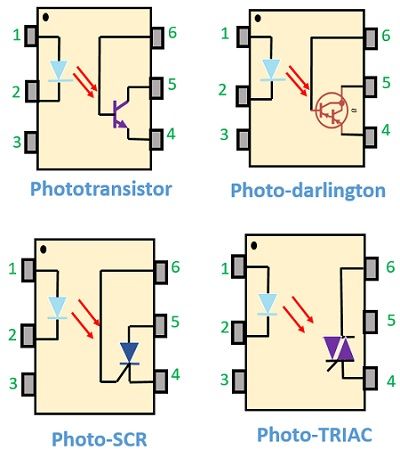
The various types of the optocoupler are shown in the diagram given below:

For the use in DC circuits, photo-transistor and photo-Darlington devices are majorly used. In the case of AC, powered circuits photo-SCR and photo-TRIAC are used.
There exist some other forms of source-sensor configurations like LED-LASER, LED-photodiode, reflective optocoupler, slotted optocoupler etc.
Advantages
- Optocouplers allow easy interfacing with logic circuits.
- Electrical isolation provides circuit protection.
- It allows wideband signal transmission.
- It is small in size and lightweight device.
Disadvantages
- The operational speed of Optocouplers is low.
- In case of a very high power signal, the possibility of signal coupling may arise.
Applications
- It is used in high power inverters.
- It is used in high power choppers.
- In AC to DC converters optocouplers are widely used.
The layout of an optocoupler depends basically upon the isolation voltage. To have the appropriate breakdown voltage the optical channel is made as thin as possible.
Leave a Reply