Definition: Single Tuned Amplifiers are multistage amplifier circuit that employs a parallel tuned circuit as a load. However, the tuned circuit in each stage is required to be tuned to similar frequencies. A common emitter configuration amplifier can be used as a single tuned amplifier which includes the parallel tuned circuit.
During wireless communication, the radio frequency stage requires a tuned voltage amplifier in order to select the desired carrier frequency and amplify the allowed passband signal.
Constructional details of a Single Tuned Amplifier
The figure below shows the circuit arrangement of a single tuned amplifier with capacitive coupling.
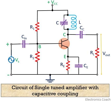
It is noteworthy here that for a tuned circuit, capacitance and inductance value must be so selected that the frequency of resonance must be equivalent to the frequency of the applied signal.
We can get the output of the circuit either by capacitive or inductive coupling. However, here we have used capacitive coupling.
The capacitor CE employed in the circuit is a bypass capacitor whereas biasing and stabilization circuits are followed by R1, R2 and RE.
Tuned LC circuit employed in the collector region acts as the load. In order to have a variable resonant frequency, the capacitor is variable. Large signal amplification can be obtained if the frequency of input signal is similar to the frequency of resonance of the LC circuit.
Operation of Single Tuned Amplifier
The circuit operation of single tuned amplifiers begins with the application of the high-frequency signal that is to be amplified at the base-emitter terminal of the transistor, shown in the figure above.
By varying the capacitor employed in the tuned circuit, the resonant frequency of the circuit can be made equivalent to the frequency of the applied input signal.
Here, the high impedance is offered to the signal frequency by the tuned circuit. Thus, a large output is achieved. For an input signal with multiple frequencies, only the frequency that corresponds to resonant frequency will get amplified. While all other frequencies are rejected the LC circuit.
Hence, only the desired frequency signal gets selected and thus amplified by the circuit.
Voltage gain and frequency response
For a tuned amplifier, voltage gain is given by
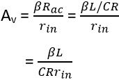
: Rac= impedance of tuned circuit
z = L/CR
rin= input impedance
Let us now move further and have a look at the frequency response curve shown below:

As we know that the impedance of the circuit is very high and is entirely resistive in nature at the frequency of resonance.
Thus, the maximum voltage is obtained across RL for a circuit tuned at the resonant frequency.
The bandwidth for a tuned amplifier is given as![]()
Any frequency within this range will be amplified by the amplifier.
Cascading effect on bandwidth
Cascading of multiple stages of a tuned amplifier is basically done, to improve the overall gain of the system. As the total gain of the system is the result of the product of gain of each stage of the amplifier.
As we have already discussed in Tuned amplifiers that increase in voltage gain results decrement in bandwidth. So, let’s proceed to have a look that how cascading effects the overall bandwidth of the system.
Consider a cascade connection of n stages of a single tuned amplifier. The relative gain of the amplifier corresponding to the gain of the system at the resonant frequency is shown by the below given equation:
: Qe is an effective quality factor
δ represents fractional variation in frequency
On combining the gain of several stages of tuned amplifier, the overall gain will be,
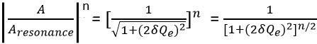
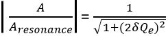
By equating the overall gain to 1/√2 we can conclude the 3-dB frequencies for this amplifier.
Thus we will have![]()
Form the above equation we can have,
![]()
On transposing 1 to RHS
![]()
As is fractional variation in frequency so we can write
On substitution of the previously given equation, we will have,
![]()
Or we can write,![]()
Now,![]()
and![]()
The bandwidth of tuned amplifier with n number of cascaded stages is given as
![]()
On substituting the values, we will have
![]()
The above equation can be written as![]()
We know BW for the single stage is given as
So, we can write![]()
From the above equation, we can say that ‘n’ stages bandwidth is basically equivalent to the product of single stage bandwidth and a factor
If the number of stages is 2, then ![]()
Similarly for n = 3, ![]()
Hence, from the above discussion, it is clear that bandwidth decreases with the increase in the number of cascaded stages.
What is potential instability in tuned amplifiers?
It is basically a limitation of tuned amplifiers, that results in the bad reproduction of signals.
As it is already known that a tuned amplifier must possess highly selective nature. But, for the circuit to be highly selective, the Q factor must also be high.
This high Q will provide a high voltage gain with the reduction in bandwidth. This is due to the inverse relation of bandwidth with respect to Q factor.
So, we can say, reduction in bandwidth will deteriorate the quality of amplification. Due to this, the complete band of the signal will not be equally amplified. Thereby, resulting in the bad reproduction of the signal. This is known as potential instability.
Leave a Reply